")
We have posted various articles for people who love electronics and have basic or advanced knowledge of electronics. But we at DNA Technology never thought about small kids (bad bad DNA) who have no knowledge of Electronics and to whom we can teach electronics practically and get them involved & like Electronics. We are very grateful to our new guest Blogger Mrs Alka Verma from Electronic is Fun for pointing this out and writing this very simple decorative project that will generate spark for learning Electronics in small kids.
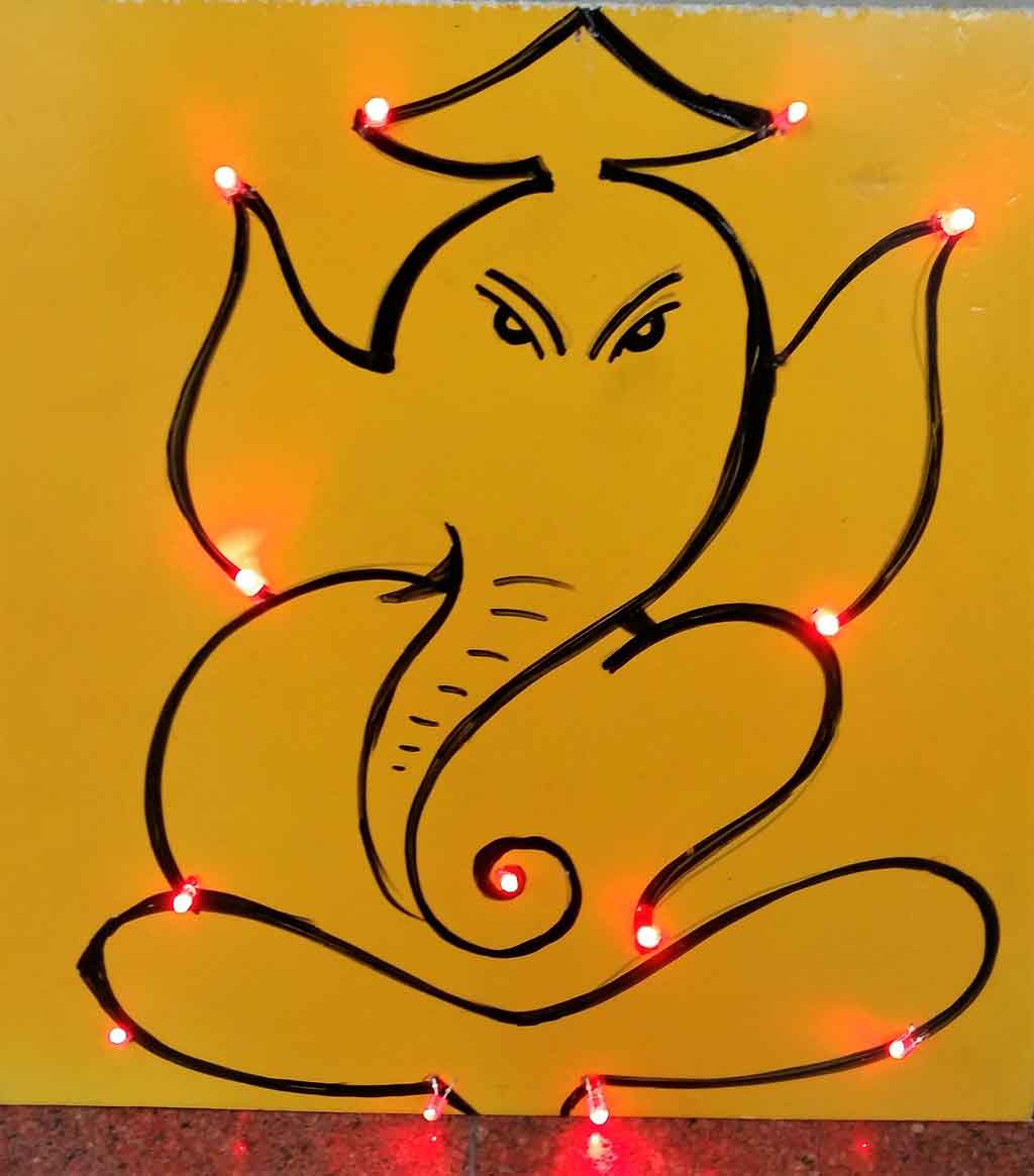
In this activity we will be making a LED Decorated Ganesha. In this we will be joining LED's in parallel connection by soldering to make an interesting display. Parallel connection means the positive terminal of all the LED's will be joined together and all the negative terminals will also be joined together with the help of soldering using connecting wire. If one of the LED's is not working or not connected properly, this will not affect the whole circuit. Remaining LED's will keep glowing. The circuit is powered by two pencil cells.
Material Needed:
- Vinyl board or card board.
- LED's
- Solder Iron
- Solder Metal
- Wires
- Cell Holder
- Pencil Cell
- Cutter & Stripper
Step By Step Procedure
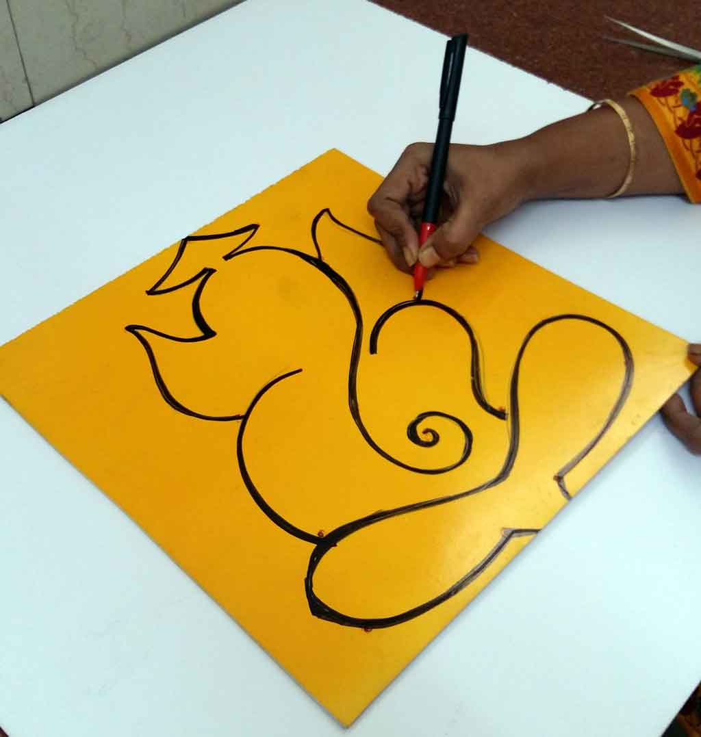
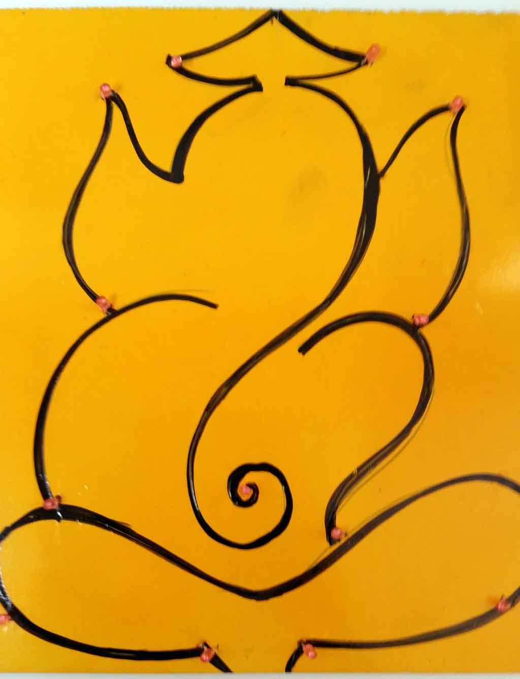
1. Take half card board and draw anything which interests you, it can be a religious symbol or any cartoon character.
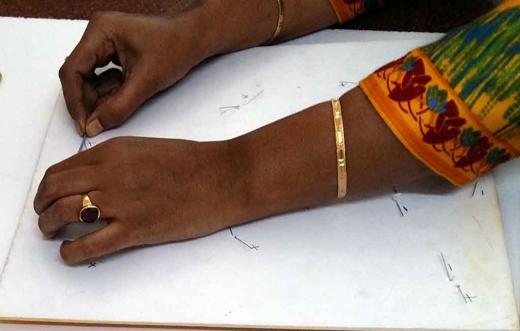
2. Mark the dots on places where you want to put the LED'ss. Using Tweezers make two holes at place where an LED is to be placed. Insert the LED's in the holes.
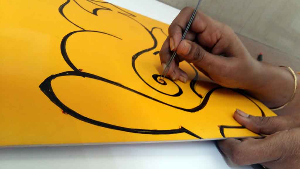
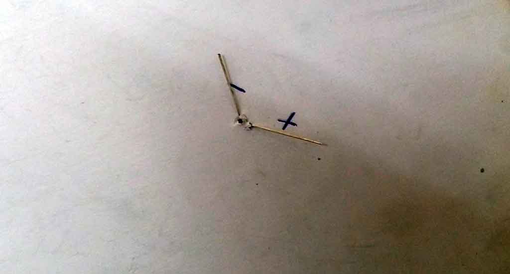
3. Turn the board and bend the legs of LED. Mark the longer leg as ‘+’ (positive) and shorter as ‘-‘ (negative).
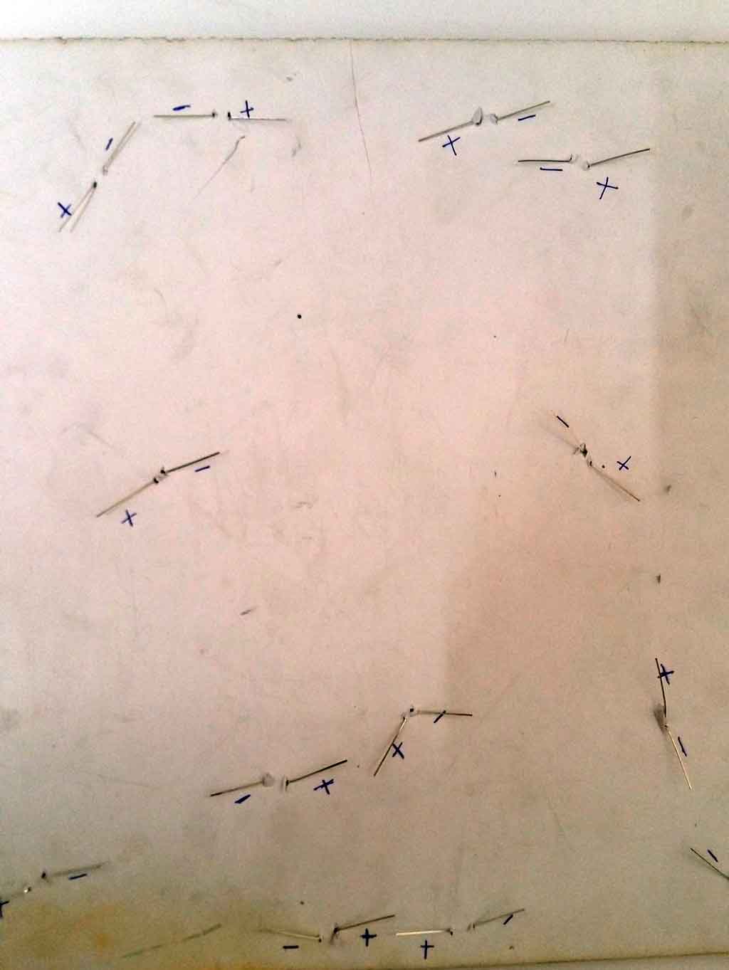
4. Likewise place all the LED's on the board and mark all positive and negative terminals.
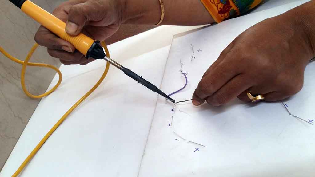
5. Turn On the Soldering iron, clean the iron bit and let it heat. Till then measure the length of the wire needed to join positives of the two nearby LED's. Measure the length of insulating wire such that the legs of LED's are connected comfortably. They should not stretch.
6. Cut the wire slightly bigger then that length
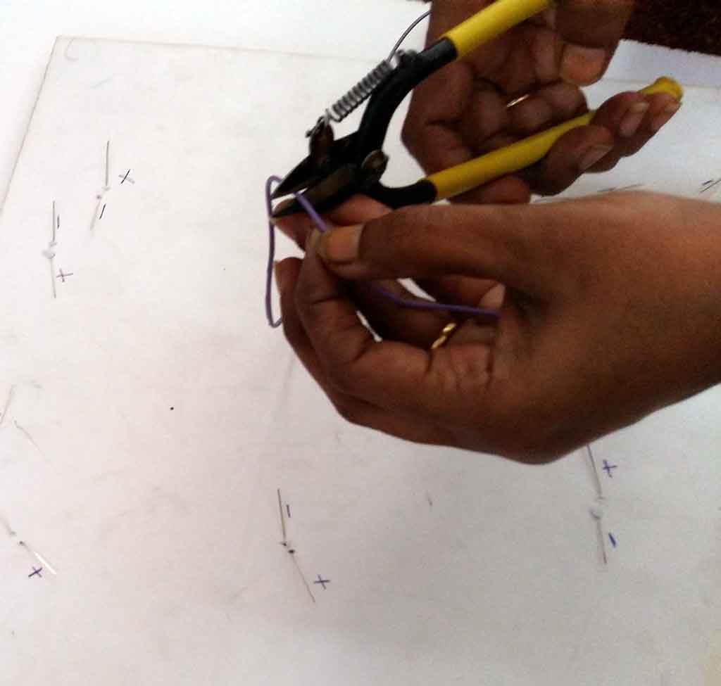
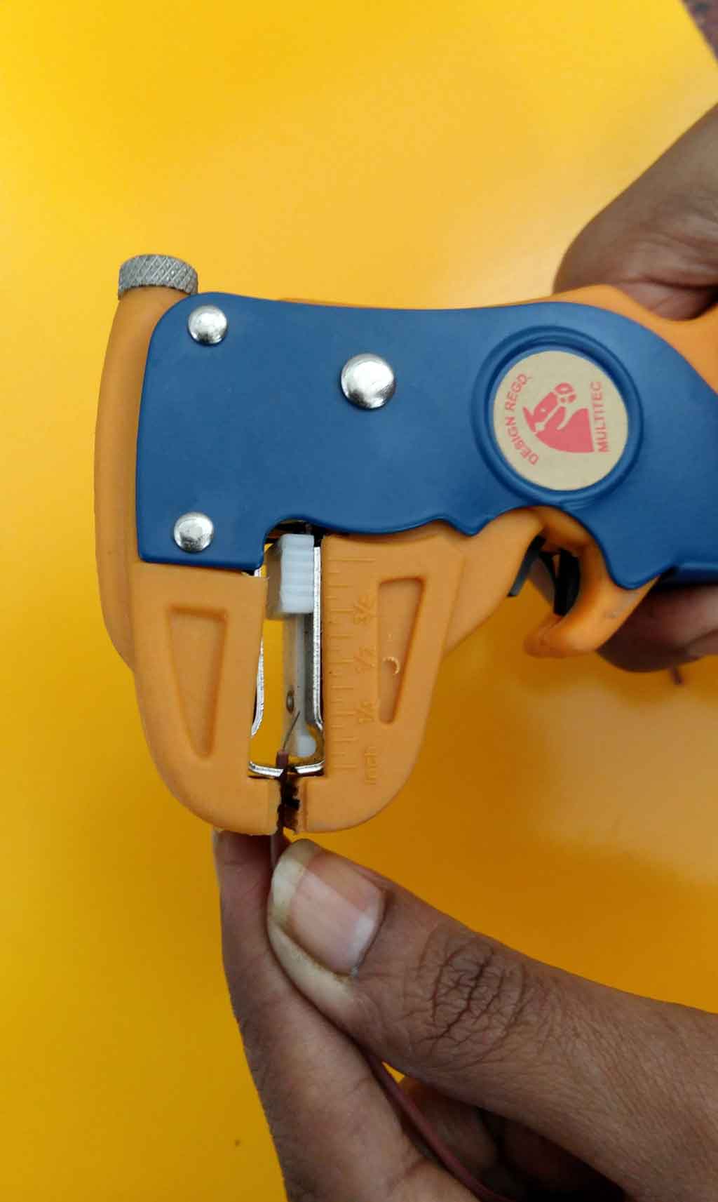
7. Now Peel 1 cm insulation from both ends of the wire using wire stripper.
8. Now Wrap the uninsulated part of wire on the positive lead of the LED. You need two wires to be connected on to the LED’s leg, so wrap both the wires simultaneously and fix it on the lead.
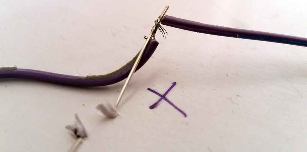
9. Check the soldering iron using solder wire – if it melts, the iron is ready. Hold the iron as you hold a pen or pencil in your active hand and solder wire in the other and solder the connection. If you have never soldered before check How to solder.
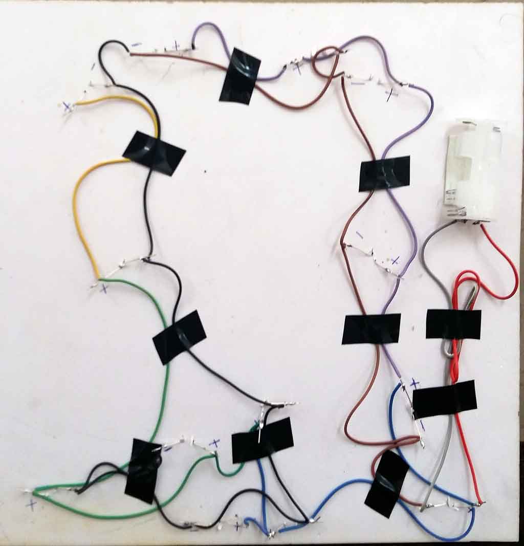
10. Likewise, join all the positive leads of the LED together.
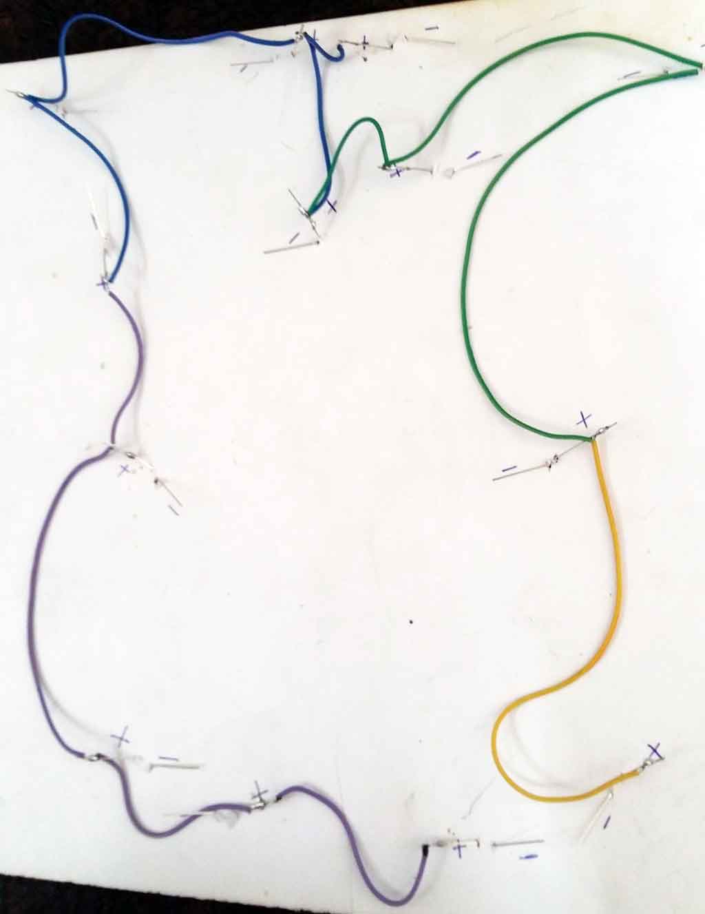
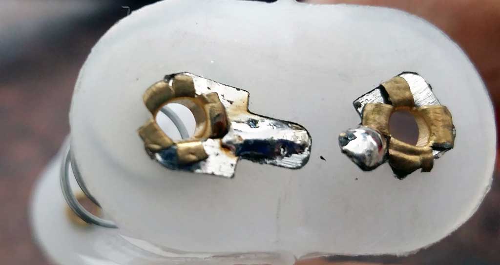
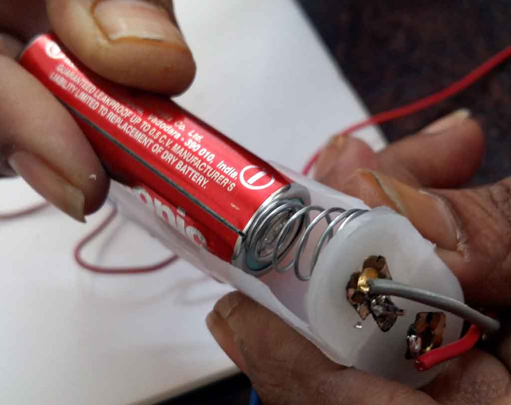
11. Start the same procedure and join all the negative leads of the LEDs. Now we need to connect all the LEDs to two pencil cells through cell holder. Soldering on cell holder is very critical to the circuit and needs a lot of skill.
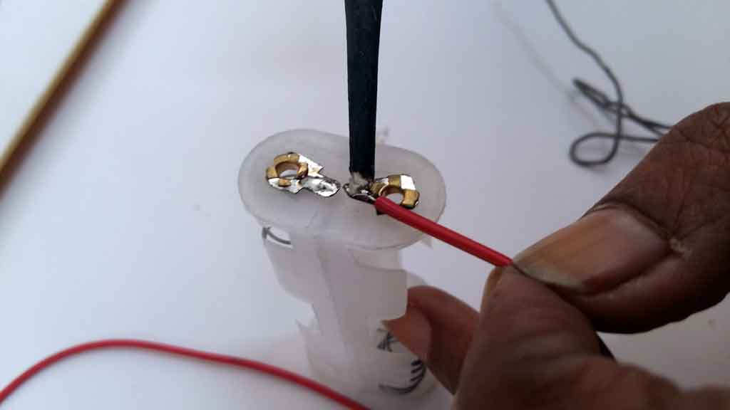
12. Steps to solder cell holder. A cell holder has two metallic edges at one end. Hold the cell holder such that metallic edges face upside. Put some solder on these metallic edges. Care should be taken that hot solder iron does not touch the plastic body of the cell holder.
13. Take two connecting wires preferably of different colors. Prepare them for soldering (cut, peel, wrap). Apply some solder wire on the uninsulated part of the connecting wire using hot iron. This process is called tinning.
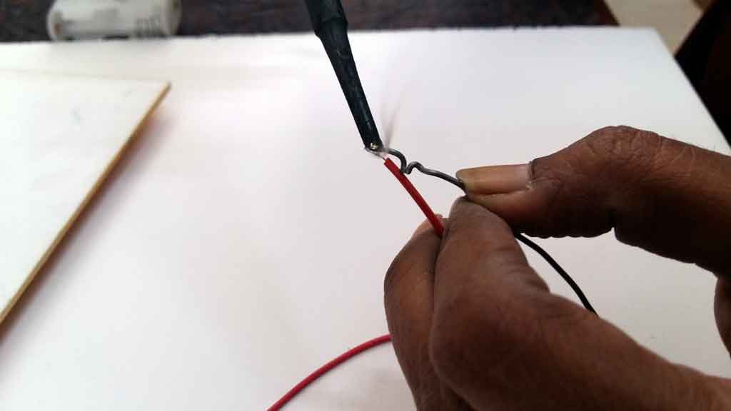
14. Now keep this wire on one of the metallic terminal of the cell holder and using soldering iron, join the wire to the terminal. Similarly join other wire to the other terminal of the cell holder.
15. The terminal of the cell holder with the spring attached, is the negative terminal. We have joined grey wire to the negative terminal. So grey wire is negative and red wire is positive.
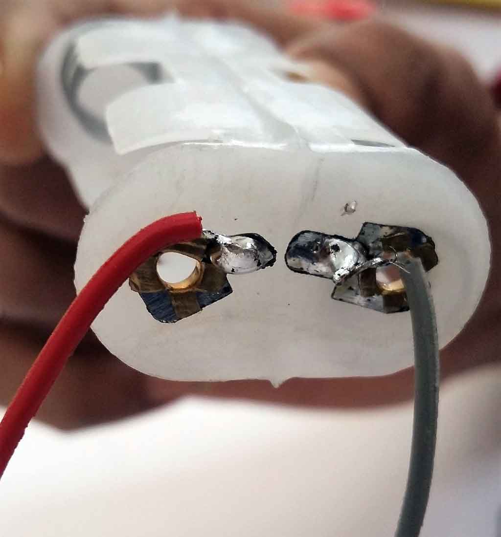
16. Connect the positive terminal wire (RED) of the cell holder to the positive leg of any of the LED and connect the negative terminal (spring side) wire of the cell holder to the negative lead of any of the LED.
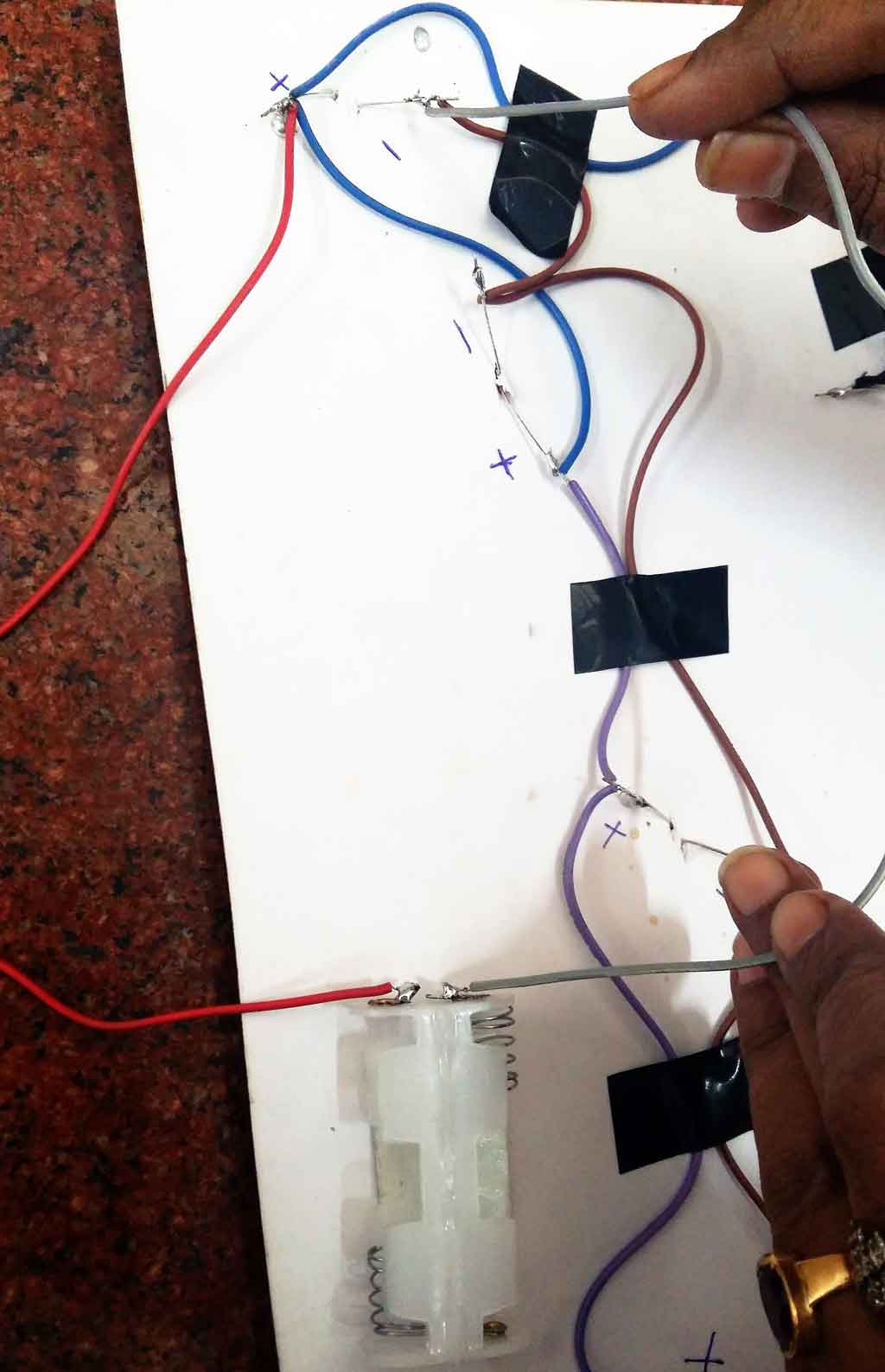
17. Fix all the wires on the LED board using insulating tape to prevent them from entanglement.
18. Insert cells in the cell holder (Flat side of the cell to the spring side of the holder).
All the LED will start glowing. Isn’t it cool !!!!
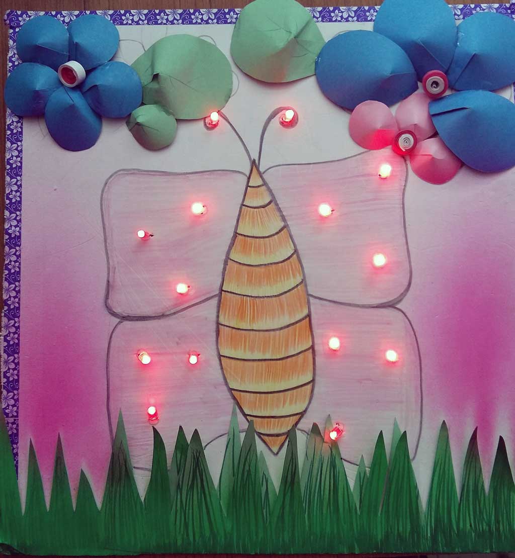
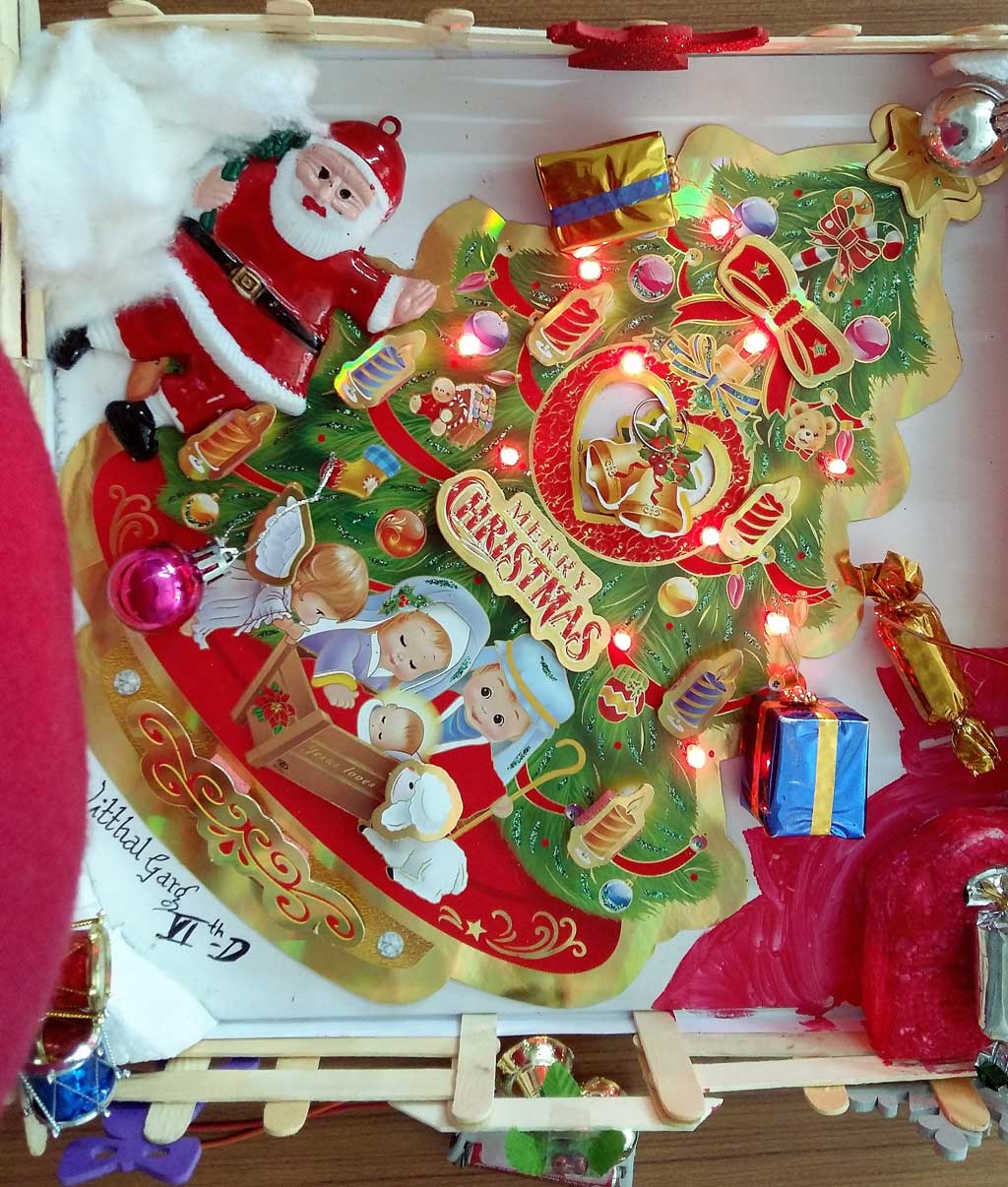
Small kids have also made some more creative designs below are some more designs