")
 Want to interface LCD & Keypad to Arduino but don’t want to do all that wiring? Well then this LCD Keypad Shield for Arduino is perfect for you. It has a 16x2 Alphanumeric LCD with white characters & blue backlight. It also has a keypad with 5 switches. In this tutorial we will learn basics of the LCD & keypad shield.
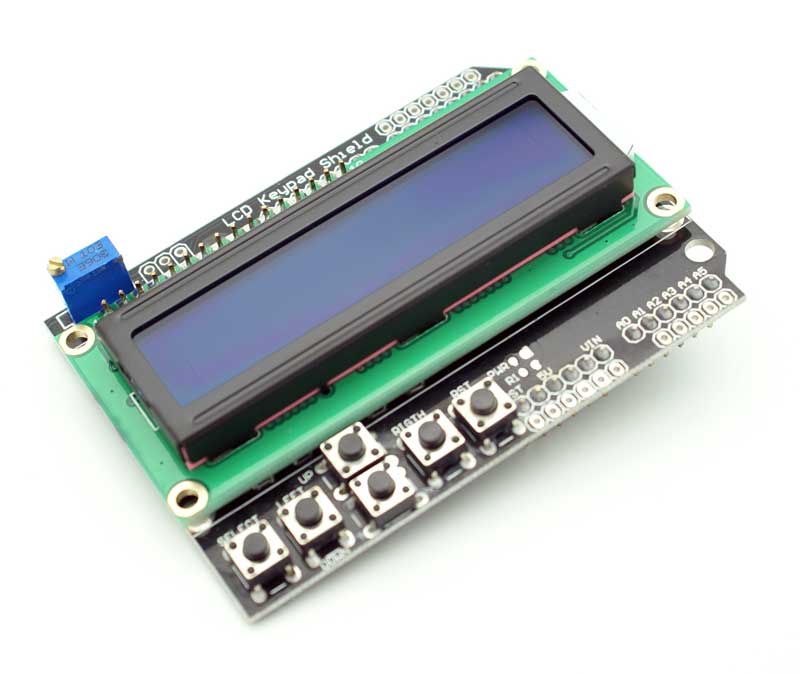
The main reason this Arduino LCD shield is easy to use is because it is fully compatible with the LiquidCrystal Arduino Library. All you have to do is just change the Pin numbers of the LCD from the sample LCD code and you are ready to go.
Another major advantage of this LCD & Keypad Shield is that the switches are all connected to only one ADC channel. That’s right only one pin is required to read which one of the five switches is pressed. The pressed switch can be detected by reading analog value trough a 5 stage voltage divider circuit. The shield also has onboard contrast control pot. You can also control the back-light intensity or turn it ON & OFF via Arduino.
Compatibility
LCD & Keypad Shield is compatable with following Arduino Boards:
- Arduino UNO
- Arduino Mega2560
- Arduino Diecimila
- Duemilanove
Power Required
The LCD & Keypad Shield requires 5 volt power supply. It worked well when I used external adaptor but while using USB supply it works well most of the time. Sometimes if my PC’s USB is also powering some devices then the current required for the back-light control may decrease also this may cause voltage to drop & the 16x2 Alphanumeric LCD may not work properly. So make sure you are not powering lot of devices via USB port.
LCD & Keypad Shield Pin Allocations
- A0 : All five Switches (Select, Up,Down, Left, Right)
- D4 : LCD DB4
- D5 : LCD DB5
- D6 : LCD DB6
- D7 : LCD DB7
- D8 : LCD RS
- D9 : LCD Enable
- D10: LCD Backlight Control
Want to interface LCD & Keypad to Arduino but don’t want to do all that wiring? Well then this LCD Keypad Shield for Arduino is perfect for you. It has a 16x2 Alphanumeric LCD with white characters & blue backlight. It also has a keypad with 5 switches. In this tutorial we will learn basics of the LCD & keypad shield. Another major advantage of this LCD & Keypad Shield is that the switches are all connected to only one ADC channel. That’s right only one pin is required to read which one of the five switches is pressed. The pressed switch can be detected by reading analog value trough a 5 stage voltage divider circuit. The shield also has onboard contrast control pot. You can also control the back-light intensity or turn it ON & OFF via Arduino.